After hearing about the G-35 holiday lights, and particularly after being sent to "deep darc" though Hack-a-Day, I set out on my own project, ostensibly to win a bet for the snazziest Xmas boat decorating.
Warning: This is a work in progress, so you might not want to rush into using my code or duplicating my hardware until we see how it ends!
Another warning: I have no "source control" for files available here. They may get updated without warning as my debugging progresses. I'll try to indicate when I make changes, but I'm unreliable!
I had set up some eBay searches to look for the 50-light strings, and one day I found a vendor that was selling them for $20 with Buy-It-Now, so I set up a script to discover the listing faster than provided by eBay, and managed to buy seven of them before the seller came to their senses and returned to $99 prices (not sure what happened there!). My plan included the need for eight strings, so I bought one additional string at Costco Online (for $74.99). In September, another vendor put a whole slew of the 36-light versions on sale for $0.99, and I managed to get a few of them for less than $3 before the rest of the world found the listings, and drove the prices up over $20. These will be my spares.
Without thinking everything through, I decided to prototype a PIC18F based controller. This first iteration was designed to drive all eight strings from an 8-bit I/O Port on the PIC. The serial protocol, as described by Darco (Thanks, Darco!) is non-standard, but very low speed, so implementing it in PIC software was easy. The serial driver is just a high-priority interrupt, that's able to drive the entire port (or any combination or bits) according to a mask value. I'm pretty sure the routine could be refined to drive all eight lines with independent data, but I've since abandoned the whole approach (for now, at least) so it's remains to be tried. Anyway, using a single string for debugging, I soon realized that specifying which LED should do what could become pretty data-intensive, so I implemented a "control language" that includes nesting, abreviated formats, and a buffer for pre-set operations (such as dimming a given LED over time).
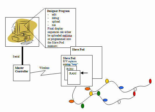
Moving on the exact implementation of all eight strings, it suddenly dawned on me that the "wiring" would be nightmare. Each configuration (a tree shape, a 20x20 sign, etc.) would require custom cabling, all of which must distribute 2-3 amps at 5.6 volts, in addition to possibly needing line drivers for the data line. I had actually gone to the trouble of buying a power supply and a bunch of weathertight automotve connectors to wire the whole thing up, when Version 2 came to mind.
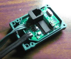
I decided to solve the cabling problem by first, keeping the AC adapter, so I only had to distribute lower current 110vac, and second, going wireless to eliminate the data issue. After a little thought, I designed a PCB that fits into the original "lump" that controls the stock product, and further decided to canabolize the stock board for the wireless component, a 434Mhz FSK receiver. My Rev0 PCB (I used Sparkfun's BatchPCB), has a couple of minor problems that I'd like to clean up before letting the design out.
The parts count is pretty low, needing only a PIC18F2620 (chosen for the large ram/prom quantity), a resonator, low-dropout regulator, a couple of decopling capacitors, a pullup for MCLR, and the RJ11 jack. I added a zener diode to deal with the wireless receiver's power requirements and a signal diode to shift the receiver output so the PIC could see it.
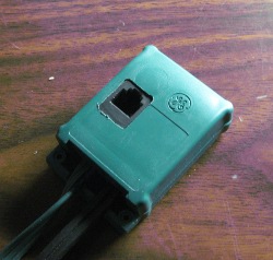
I used the standard RJ11 programming port, which sticks through the modified cover nicely. If the wireless proves reliable enough, I'll probably implement a bootloader so the RJ11 can de removed (although I need some way to program the initial part).
Each pod is programmed with an ID (actually, just an eight bit mask) which defines which LED commands it should react to, since all Pods receive the same command string. Each Pod must follow all the commands since some of the command executions result in changing the destination mask. If the final product of the execution is moot, the Pod doesn't forward the actual output to the string.
I recently re-organized my "control Language" to include using the wireless. The wireless is pretty slow (although I plan to try running it a little faster), so sending all the individual LED commands will result in pretty slow refresh times, so other approaches are needed:I designed and ordered the Pod PCBs before actually working with the stock wireless parts. I did implement the transmitter, but assumed the receiver would be similar, therefore simple. My first complete Pod had the receiver fail, due to my powering it with 5v instead of the 3v used in the original. I did discover the potting-compound-covered parts in the original were apparently some fairly sophisticated FSK decoding hardware, as I quickly discovered the receiver generates lots of random data, unsuitable to deal with as an interrupt to the PIC. I also found that as long as I keep the transmitter "on", I can elimnate the spurious data. So the adopted wireless protocol will be vaguely like the one reported by Darc, but slightly modified. Idle is a continuous string of ONE (200us on, 200us on), a START bit (400us ON, 400us OFF), followed by data (0=100/100, 1=200/200), followed by a STOP bit (600us ON, 600us OFF), then more ONEs as it returns to idle. I've since found that with a requirement for a couple of leading sync bytes, I can successfully turn off the transmitter when idle without noise problems. After using a zener diode to lower the supply voltage to the receiver, I found I had to add a switching diode in the output to allow the drive to the PIC's schmidt trigger input to work. If I was willing to build a new Pod case, I'd probably just go with the SparkFun units that include a 4800baud user interface - the receiver is too big. Or go with a Freescale MC33596 and do it from scratch.
I spent a lot of time chasing noise problems on the wireless link, and finally discovered the Maxim RS-232 chip with it's charge pump circuit was creating all the problems, so I packaged up the final installation without a PC involved, which means my development tool is out of the loop.Here's a sequence that steps through the eight primary colors, turning each consecutive LED on, with the "older" LEDs decaying to off over eight time steps, then working back the string turning the LED on solidly, followed by an erase, then the next color:
chasing: lw 0 00f- -1 ;turn LED0 red, with auto-decay set, mask=FF call sub1 ;call subroutine erase ;erase all LEDs lw 0 0ff-,-1 ;same sequence with Magenta call sub1 ;etc erase lw 0 0f0-,-1 call sub1 erase lw 0 ff0-,-1 call sub1 erase lw 0 f00-,-1 call sub1 erase lw 0 f0f-,-1 call sub1 erase lw 0 ddd-,-1 call sub1 end sub1: delay 1 ;delay 1/20th second (executes auto-decay function) sw + ;write next LED jmpc sub1 ;repeat until 50th LED lit delay 1 flush ;stop the "auto-decay" process clrd ;clear the "auto-decay" bit in the RED field sub1a: sw - ;write previous LED delay 1 jmpc sub1a ;loop until LED0 lit return |
The above code compiles to 70 bytes of PIC memory, yet generates 807 commands (at 5 bytes each) to the LED string.
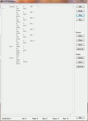
Updated 11/21/2011. I've updated the compiler to do the whole job at once. Here's the exe and here's the au3. Either needs this DLL file to work with a serial port. As shown to the left, it provides an edit window where you write the sequence, allows you to compile it, and either single step through it for debugging, save it as an include file (just a bunch of "db" directives for MPASM), or upload it directly to the PODs. It's written using AutoIt3, which is a pretty cool scripting language. The old stand-alone compiler is here (exe) or here (au3).
Here's my current Pod software (updated 11/21/2011). Everything is working, although as I write new display sequences, I keep finding things I want to add. Some of the recent additions are a deeper stack for subroutines, hardware blink, a "momentary" write, and a background color.
I expect to expand the compiler to understand colors by name (e.g. Magenta), and LED addresses by their physical location in the display rather than address/mask values. The latter would require a cross-reference table to describe the relationships. For example, for my boat display, I might rather call LEDs by S1, P2 (starboard #1, port #2). The best feature of this mapping would be to allow stringing lights as convenient rather than to maintain symetry.
Another obvious task is an Optimizer that would allow you to design sequences with brute force, and it could figure out where the shortened forms of the Protocol could be used.
As a side experiment, I've explored the possibility of creating a Mega-Tron type setup with trivial hardware. I've written the driver for one PIC18F processor to drive sixteen strings of lights at once. Running at 40mhz, the driver consumes 70% of the CPU resoources, leaving the other 30% to implement a simple graphic and character controller. I think SparcFuns 40Pin PIC/USB (serial) DEV-0022 might be a suitable choice.
Waitiing more time and energy is re-programming the 8051-type controller in the stock "pod" to do what I want. I think it would be easy to replace the existing code and have data patterns uploaded via the existing wireless hardware. The plastic case would need to be opened to re-program the processor (using the test points provided). I haven't worked with an 8051 for many, many years, and I don't have any of the tools installed (yet).
Update 12/22I downloaded all the tools, refamiliarized myself with the 8051, and tried in vain to get the stock part to accept re-programming. It refused, so either the manufacturer uses a special fixture or locked out the possibility of overwriting the code. Given the difficulty of working with Chinese tools with no English manual, I think I'm declaring this effort dead!
Update 11/1/2021My wife was bugging me to put these lights up in a real tree, and after the noisy results using the 433mhz parts salvaged from the original pods, I bought a bunch of Lc12s bluetooth transceivers, which fit nicely with no mdification except adding a 3.3v regulator hanging in space. The 2021 display is not rock solid, never gets out of sync, and as far as I know doesn't disrupt my neighbor's life. Of course I had to re-code quite a bit to tear out the software fsk receiver and replace it with the regular uart.
Email me at jjgurleyATgmailDOTcom